Working stress method
The working stress method is a traditional method that is mainly used for reinforced concrete as well as for structural steel and timber design. This method obeys Hook’s law, which means that the stress is directly proportional to strain up to the point of collapse.

The main assumption of this method is that the structural material behaves in a linear elastic manner and that adequate safety can be ensured by suitably restricting the stresses in the material induced by the expected working load on the structure. It also assumes that the concrete and steel reinforcement act together and are perfectly elastic in all stages.
In this method, the specified permissible stresses are kept below the material strength. The factor of safety which is provided for possible overloads is the ratio of the strength of material to the permissible stress.
Principle of working stress method
The main principle of the working stress method is that it works under the assumption that structural materials behave in a linear elastic manner and also can ensure adequate safety by suitably restricting the stresses in the material induced by the expected working load on the structure.
\[\text{Permissible}\,\,\text{Stress=}\frac{\text{Ultimate}\,\text{or}\,\text{yield}\,\text{stress}}{\text{Factor}\,\text{of}\,\text{Safety}}\]
\[\text{Working Stress }\le \text{ Permissible Stress}\]
But the working stress method does not provide a realistic measure of the actual factor of safety for a design and also fails to discriminate between different types of load that act simultaneously. But some of the advantages is that the structures designed based on the working stress method have larger safety factors than in the limit state method.
This method is simple in concept as well as application. Still, the working stress method is accepted in India for special structures such as RC bridges, water tanks, and chimneys.
Also Read: Modulus of Resilience
Limit state method
Limit states method was introduced as an advancement over the traditional design philosophies. The acceptable limits of safety and serviceability requirements before failure occur are called a limit state. The working stress method was based on calculations on service load conditions whereas the limit states method aims for a rational and comprehensive solution to the design problem, by considering serviceability at working loads and safety at ultimate loads.
There are two important limit states to be considered in the design:-
- Limit state of collapse
- Limit state of collapse deals with strength, overturning, sliding, buckling, etc.
- Limit state of serviceability
- Limit state of serviceability deals with discomfort to occupancy caused by excessive deflection, crack width, vibration, leakage, etc.
Principle of limit state method
The philosophy of multiple safety factor format is made use in limit state method which attempts to provide adequate safety at the ultimate loads as well as adequate serviceability at the service loads, by considering all possible limit states.
The limit state is also defined as a state of impending failure beyond which a structure ceases to perform its intended function satisfactorily in terms of either safety or serviceability either collapses or becomes unserviceable.
The loads obtained from multiplying characteristics loads with suitable factors of safety should be used to design the structures and also depending on the nature of loads or their combinations. These factors of safety for loads are termed partial safety factors for loads.
\[\text{Design load }{{F}_{d}}=\text{ }\left( \text{Characteristic load }F \right)\times \left( \text{Partial safety factor for load }{{\lambda }_{f}} \right)\]
Difference between working stress method and limit state method
| WORKING STRESS METHOD | LIMIT STATE METHOD |
| In the working stress method, it is assumed that the structure has failed when it reaches the elastic limit | In limit states design, it is considered that the structure is failed only when it reaches the lower yield point |
| A stress-based method | A strain-based method |
| The material follows Hooke’s law so the term elastic is used. | In this method, the material is allowed to go beyond the yield limit |
| Uneconomical approach to simple designs or other structural elements where stress is the design criteria | Design is more economical |
| The factor of safety is used | The partial factor of safety is used |
Advantages of limit state method over working stress method
- It’s an advancement of traditional philosophies and uses a method of design of the structure that considers a wide range of logical and technical considerations.
- It’s an economical design of the structure as compared to other methods
- Different kinds of failure, types of materials, and types of loads are considered in this method.
Modular Ratio
The Modular ratio in the working stress method is the ratio between the moduli of elasticity of steel and concrete and it can be used to determine the stresses in steel and concrete.
Factor of safety in working stress method
The factor of safety which is provided for possible overloads is the ratio of the yield stress of material to the permissible stress. The factor of safety can be used to define the permissible stress, which takes care of the overload or other unknown factors.
\[\text{Factor}\,\text{of}\,\text{Safety}=\frac{\text{Ultimate}\,\text{or}\,\text{Yield}\,\text{stress}}{\text{Permissible}\,\text{Stress}}\]
Assumptions of working stress method
The basic assumptions based on the linear elastic theory are:-
- A plane section of a structural element remains plane before and after bending
- The strain-stress relationship for concrete and steel under design loads is linear
- The tensile stress resistance of concrete in bending is zero, except specifically permitted
The Modular Ratio, \(m\,=\,\frac{280}{3{{\sigma }_{cbc}}}\)
Design a rectangular water tank by working stress method

(a) Permissible stress according to the grade of steel and concrete
\[\begin{align}
& \to \ \ {{\sigma }_{cbc}}=\ \ \ \ \ \ \ \ \ \ \ \ \left( \text{IS 456} \right) \\
& \to \ \ {{\sigma }_{st}}=\ \ \ \ \ \ \ \ \ \ \ \ \ \left( \text{IS 3370} \right) \\
& \to \ \ {{\sigma }_{ct}}=~~~~~~~~~~~~~~~\left( \text{IS 456} \right)~~ \\
\end{align}\]
(b) Dimensions of water tank
- \(\text{Volume}\,\text{=}\,\frac{\text{Capacity}\,\text{in}\,\text{litre}}{\text{1000}}({{m}^{3}})\)
- \(\text{Height}\,\text{of}\,\text{water}\,\text{=}\,\frac{\text{Volume}}{\text{Area}}\)
- \(\text{Height of tank wall = Height of water + Freeboard}\)
(c) Check \(\,\frac{L}{B}\) ratio
1. \(\,\frac{L}{B}\,\langle \,2\)
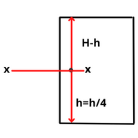
The walls are designed as a continuous slab subjected to water pressure \(\frac{H}{4}\) or 1 m from the bottom, whichever is greater.

The intensity of water pressure at section \(\,=\,p\,=\,\gamma (H-h)\)
\(\text{Where }\!\!~\!\!\text{ }=\text{unit weight of water }10\text{ }KN/{{m}^{3}}\)
- Moments
Moments in side walls are determined by the moment distribution method
(i) Fixed end moments
Long walls \(\,=\,\frac{P{{L}^{2}}}{12}\)
Short walls \(=\,\frac{P{{B}^{2}}}{12}\)
(ii) Central moment/ Bending moment at the center
Long walls \(\,=\,\frac{P{{L}^{2}}}{8}\)
Short walls \(\,=\,\frac{P{{B}^{2}}}{8}\)
Now distribute the moments using the moment distribution method also find the maximum moment.
2. \(\,\,\frac{L}{B}\rangle 2\)
Now distribute the moments using the moment distribution method also find the maximum moment.
Bending moment for long walls \(\,\,=\frac{\gamma {{H}^{3}}}{6}\)
Bending moment for short walls \(=\frac{\gamma (H-h){{B}^{2}}}{16}\)
Maximum cantilever moment for short walls \(=\left\{ \begin{align}
& M=\,\frac{\gamma H{{h}^{2}}}{6} \\
& M\,=\,\frac{\gamma {{H}^{3}}}{6} \\
\end{align} \right\}\) whichever is greater.
d. Design of long and short wall
1. Effective depth \(=\,\sqrt{\frac{M}{Q.b}}\)
\[Q\,=\,\frac{1}{2}.j.k.{{\sigma }_{cbc}}\]
\[j\,=\,1-\frac{k}{3}\]
\[k\,=\,\frac{m.{{\sigma }_{cbc}}}{m.{{\sigma }_{cbc}}+{{\sigma }_{st}}}\]
2. Overall depth =
3. Calculating forces in wall
(a) Direct Tension in long walls \(={{T}_{L}}=\frac{PB}{2}\)
(b) Direct Tension in short walls \(={{T}_{B}}=\frac{PL}{2}\)
4. Reinforcement
(i) \({{A}_{st\,\,long}}=\,\frac{M\,-\,T.x}{{{\sigma }_{st}}{{j}_{d}}}+\frac{{{T}_{L}}}{{{\sigma }_{st}}}\)
(ii) \({{A}_{st\,\,short}}=\,\frac{M\,-\,T.x}{{{\sigma }_{st}}{{j}_{d}}}+\frac{{{T}_{B}}}{{{\sigma }_{st}}}\)
(e) Floor Slab
- For floor slab, M10 concrete is enough
- Provide nominal reinforcement
(f) Draw Reinforcement details
Also Read: Complete Guide on Different Types of Beam and its Classification
FAQs on Working stress method
The working stress method is also known as?
The working stress method is also known as the Modular Ratio Method.
Why water tank design by working stress method?
🠺 Water tanks are more vulnerable and the designs are mostly conservative. The water level inside the tank varies continuously along with the pressure inside.
🠺 The working stress method is adopted because of the above and also it does not account for the variation of loads.
🠺 It has a high safety factor and offers more serviceability when compared to the limit state method


Leave a comment