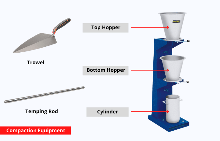
Compaction factor test procedure
- The apparatus is kept on the ground and grease is applied to the inner surface of the cylinders
- The cylinder’s weight is marked as W1, and the cylinder is connected to the base in such a way that the hoppers’ central points and the cylinder’s central points are on one vertical line, and the cylinder is covered with a plate.
- Using a hand scoop the concrete sample that is to be tested is placed in the upper hopper. The concrete is filled in the hopper till its brim and after that, the trapdoor is opened so that the concrete falls into the lower hopper
- If the concrete sticks onto the hoppers then it has to be pushed using a rod gently to fall down
- The trap door of the lower hopper is opened and the concrete is allowed to fall into the cylinder, the excess concrete on top of the cylinder is cut off using trowels
- The cylinder should be wiped clean keeping in a place that is free from vibration or shock and the weight of the concrete in the cylinder should then be determined and noted as W2.
- The weight noted is known as the weight of partially compacted concrete
- The cylinder is then replaced with concrete from the same sample in 5cm deep layers, with each layer being forcefully compressed or preferably vibrated to achieve complete compaction.
- The top surface of the fully compacted concrete should also be carefully struck off level with the top of the cylinder and the weight of the cylinder along with concrete is noted as W3.
- The compaction factor is calculated by the formula:
\[\text{CF = }\frac{\left( W2-W1 \right)}{\left( W3-W1 \right)}\]

Relation between compaction factor and workability
If the concrete has a compaction factor of 0.85, then it represents a mix of poor workability. If it has a 0.95 compaction factor then it represents medium workability and 0.95 represents good workability.
Also Read: Bleeding of Concrete
Objective concrete compaction test
The compaction factor test is designed mainly for the laboratory but can also be used in the field. It’s more precise and sensitive than the slump test and is particularly useful for concrete mixes of very low workability and normally used when concrete is to be compacted by vibration.
What is compaction equipment?
The compaction equipment has two conical hoppers having a hinged trap door attached to the lower end of each hopper, allowing the concrete sample to flow freely into the cylindrical mold. The hoppers and molds are attached to a sturdy steel frame that may be simply removed for cleaning.

Field compaction test methods
The most commonly used field compaction tests are the Sand cone method, Drive tube method, and nuclear method. Among the three the sand cone method is the most accurate one. The drive tube and nuclear method are the most time-efficient tests and are widely used by several testing agencies.
Sand Cone Method
The sand cone test is used mainly to find the in-place density of soils. The dry density test is performed in the field to ensure that the layers are properly compacted. First, the weight of the empty sand cone is taken, and then it is filled with dry sand and is weighed again. Next, the weight of excavated soil from the hole is taken. Water content must be determined from the collected specimen after the weights are noted. With the help of a base plate, the sand cone is placed on the test hole and the sand is allowed to run by opening the control valve.

The valve is closed when the sand stops running and the weight of the one with the existing sand is measured. Then calculate the dry density of the soil. If the test fails, compact, and perform the test again. For the field density test, divide the dry density of the soil by the maximum dry density from the proctor test to get the percent compaction.
Nuclear Method
A nuclear test uses a radioactive isotope source on the surface of the soil to measure the density and moisture content of the compacted soil. The dense soil absorbs more radiation when compared to loose soil when the activated isotope source gives off photons, usually gamma rays, which radiate back towards detectors on the bottom of the unit.

To test the soil a pilot hole is formed using a steel rod and then the probe containing the radioactive source is lowered into the pilot hole formed and for about a minute the radiation transmission is measured. This type of taking readings is called the direct transmission test.
Calculation of Compaction Factor Value
\[\begin{align}
& \text{Volume}\,\text{of}\,\text{the}\,\text{hole =}\frac{\text{Mass}\,\text{of}\,\text{sand}\,\text{in}\,\text{the}\,\text{hole}\,}{\text{Density}\,\text{of}\,\text{used}\,\text{sand}} \\
& \\
\end{align}\]
\[\text{Wet density =}\frac{\text{Mass}\,\text{of}\,\text{wet}\,\text{excavated}\,\text{soil}\,}{\text{Volume of hole }}\]
\[\text{Dry density =}\frac{\text{Wet density}}{\text{Moisture content of soil + 100 }}\times 100%\]
\[\text{Degree of compaction =}\frac{\text{Dry density}}{\text{Maximum dry density }}\times 10\]
Also Read : Non-Destructive Testing of concrete


Leave a comment