Introduction
The (three) 3-point bend test is conducted on flexural members of the structure such as the beam. A beam is a flexural member that is subjected to bending on the application of load. Consider a simply supported beam resting on two supports. The support may be either roller or hinged. Let us see the bending action of the beam shown in the figure below.
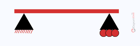
Fig 1: Simply supported beam
Consider the beam as shown in Fig 1, simply supported on hinged support on its left side and the roller support on its right side.
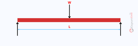
Fig 2: Simply supported beam subjected to load ‘w’
As seen in Fig 2 the load ‘w’ acting on a beam of length ‘L’ causes bending action in the beam.
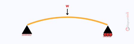
Fig 3: Deflection of the beam due to load ‘w’
As seen in Fig 3, the beam undergoes deflection due to the bending action of the load ‘w’ on the beam. This bending of the beam develops tensile stresses on the outer edge of the deflected beam and compressive stresses on the inner edge of the deflected beam as shown in fig below.
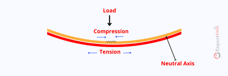
Fig 4: Bending stresses in the beam
Theory Behind 3 Point Bend Test
Three-point Bend Test procedure and working is derived from the theory of bending of the simply supported beam as explained above. To carry out the calculation of the test results after conduction of the 3-point bend test, one needs to rely on the theory of bending of the beam.
Theory of Bending
Here are a few assumptions to be made in the beam bending theory. They are:
- The material of the beam must be homogeneous and isotropic.
- The section of the beam remains plane after the bending of the beam.
- Concrete cannot take tension force. Tensile force is resisted by steel alone.
- The bond between concrete and steel in the reinforced beam is assumed to be perfect till the collapse state is achieved thus considering that strain in concrete is equal to strain in the steel.
- The beam member to be constructed must be checked for its flexural behavior and the stiffness it offers under loading. For this purpose 3- a point bend test is conducted on the beam specimen. This test is usually conducted on fibre-reinforced rectangular beams.
Also Read: Compaction Factor Test of Concrete
3-Point Bend Test
Aim
To determine the flexural stiffness of the beam specimen.
Apparatus
The arrangement of the apparatus arises from the concept of the simply supported beam subjected to the load and is by ASTM-C78.
The apparatus consists of a loading unit and a supporting unit. The load is applied by the two rollers that are connected to the head of the bending machine as shown in Fig 5 below. These rollers are resting on blocks to ensure that the load applied to the face of the beam specimen is at a right angle without developing any eccentric load.
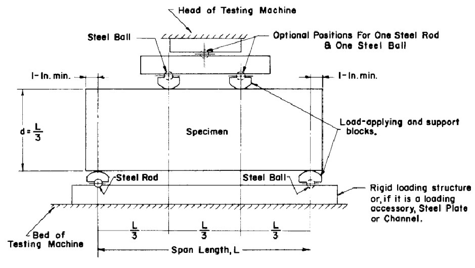
Fig 5: 3-Point Bend Test arrangement ASTM-C78
The supporting unit consists of two rollers support mounted on a steel plate to allow free movement in the horizontal direction. Hence these supports do not bear any reaction on the beam in the horizontal direction. The roller supports also tend to rotate freely.
They give only a vertical reaction to the beam specimen. The distance between the loading rollers in the loading unit and the distance between the roller support in the supporting unit must be constant and can vary only by +1.3mm or -1.3mm ( Cl 4.2.1 of ASTM- C 78) in the process of testing the beam specimen.
The loading rollers apply in the middle third span of the beam specimen ( at a distance of L\3 from the ends of the beam) as seen in Fig 5.
As per Cl4.2.2 of ASTM-C78 it must be ensured that the ratio of the distance between the applied load and the nearby support reaction (the horizontal distance) to the depth of the beam must be 1.0 and can vary only by +0.03mm or – 0.03mm.

The blocks of loading and supporting units must not be more than 64mm in height from the central axis of the pivot and these blocks must extend across the width of the specimen ( Cl4.2.3 of ASTM -C 78). The loading block and supporting block must be held in the vertical direction and are connected to the balls of the rollers using spring screws.
Test Specimens
The beam specimen to be tested must have a rectangular section. The surface of the casted specimens must not have any holes, or indentations and must have a smooth finish.
The specimens must be cast according to the sizes of the cast specified in ASTM standards ( C42, C31 or C 191). As per the ASTM standard, the sides of the specimen must be at right angles to the top and bottom of the apparatus.
Procedure
The test should be carried out on the cured specimen that has a still moist surface. Because the surface of the beam specimen is dried then the measured flexural strength value is reduced.
If the specimens are cast in the moulds then we need to keep the same surface of the specimen under the loading unit as it was when cast in the mould.
Now the loading unit must be adjusted such the loads are applied in the middle third of the beam span. The loading block is now brought in contact with the surface of the specimen and the load is applied within the range of 3 to 6 % of the calculated ultimate load.
The load is applied at a gradual rate and the corresponding deflection is read from the gauge. The load is applied at continuous intervals till the beam fails.
Basically, as per ASTM-C78, the load is applied to increase the stress at the extreme fibre of the specimen at the rate of 0.86 to 1.21 MPa\min.
The rate of loading is calculated using the following equation:
\[r=\frac{Sb{{d}^{2}}}{L}\]
where:
r = rate of loading applied
S = rate of increase of extreme fibre stress in Mpa\ min
d = average depth of specimen in mm
b = average width of the specimen in mm
L = span of the specimen in mm.
Results and Calculations
The dimensions of the failed specimen must be noted down. Measure the width and depth of the failed specimen across any one fractured face.
Measure each dimension thrice, one at the centre of the face and at the edges and determine the average width and depth that are used to calculate the modulus of rupture which in turn determines the flexural rigidity of the beam.
The formula for modulus of rupture:
1. If a fracture occurs in the middle third span of the beam on the tension side then the modulus of rupture is given by
\[R=\frac{PL}{b{{d}^{2}}}\]
Where:
R = Modulus of Rupture (Mpa)
P = Ultimate load taken from the test (N)
L = Length of the beam in mm
b = Average width at the fractured face in mm
d = Average depth at the fractured face in mm.
2. If the fracture on the tension side occurs beyond the middle third span of the beam by not more than 5% of the span of the beam then the modulus of rupture is calculated as
\[R=\frac{3Pa}{b{{d}^{2}}}\]
where:
a = average distance between the fracture line and the nearby support measured on the tension side of the beam in mm.
Note: If the fracture on the tension side of the beam is far behind the middle third span of the beam, ie more than 5% of the span of the beam, then the results are inaccurate and not valid.
Conclusion:
Hence, after getting the modulus of rupture value from the 3-point bend test, the stiffness of the beam under bending action can be determined using flexural rigidity.
Differentiation between the tensile test and 3-point bend test
The tension test is carried out on the beam only to access the rigidity of the beam when subjected to axial load.
This test measures the rigidity in terms of young’s modulus by a graphical method which can be used to characterise the material of building in terms of their stiffness and is not capable to measure the behaviour of the beam in bending cannot be measured using the tensile test.
Therefore for that, we need to conduct a 3-point bend test to determine the stiffness of the beam in bending action.
Difference between 3-point and 4-point bending test
In the 3-point bending test, the area offered under the applied load to withstand the stress is less as compared to the area offered in 4- the point load bending test.
As a result, the distribution of maximum stress is more uniform and wider in the 4- the point bend test as compared to the 3-point bend test.
Also Read: Flakiness and Elongation Index Test for Aggregate


Leave a comment